


GSMicro Primary Agent DC Gate Driver N531
- Model:
- N531
- Brand:
- GSMicro
- Batch No:
- N531, 栅极驱动IC, 单通道驱动, 推挽驱动, IGBT驱动, MOSFET驱动, 小家电功率驱动, 广晟微, SOT23-5, TO94
- Desc:
- N531 single-channel gate driver IC with 5~18V wide supply, ±500mA peak push-pull current, non-inverting output, up to 350KHz switching. Direct replacement for discrete transistor push-pull circuits. Ideal for IGBT/MOSFET driving in small appliances, SMPS,
- Stock:
- 500000 只
N531 Single-Channel DC Gate Driver IC | IGBT/MOSFET Power Switch Driver Solution for Small Home Appliances
The N531 is a domestic low-voltage non-isolated single-channel DC gate driver controller, specifically designed for amplifying weak logic signals from MCUs. It integrates a complementary push-pull output stage internally, capable of directly driving N-Channel MOSFETs, IGBTs, as well as small DC relays. Operating from a 5~18V wide DC supply, the device features non-inverting input-to-output signal transmission, eliminating the need for external inverter circuits. It replaces traditional push-pull circuits built with 4~6 discrete transistors and resistors, significantly simplifying PCB layout and reducing overall BOM costs. It is well-suited for low-voltage power control applications such as induction cookers, blenders, DC-DC switching power supplies, and small variable-frequency fans, with stable operation across a -20℃ to +85℃ temperature range.
※ Note: The IC is designed for N-Channel power devices only and does not support PMOS. For load gate capacitance exceeding 10nF, an operating frequency ≤50KHz is recommended to minimize switching losses and thermal rise.
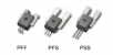
Full Product Description: The N531 is available in two mature package options: SOT23-5 (SMD) and TO94 (through-hole). It integrates an internal voltage divider comparator and an 8Ω matching output resistor, requiring only a single power supply bypass capacitor for operation—no external gate current-limiting resistor is needed. With a typical propagation delay as low as 0.1μs and fast charge/discharge capability, the device significantly reduces IGBT/MOSFET switching losses and overall system temperature rise. The product is mature in high-volume production, RoHS compliant, and offers extremely low unit cost in volume, eliminating the inconsistency and assembly complexity of discrete components. It is the preferred domestic solution for power driver applications in small home appliances.
N531 Package & Packaging Ordering Information
| Part Number | Marking | Package | Standard Packing |
|---|---|---|---|
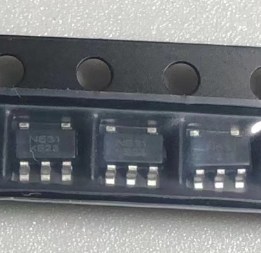
| N531 | N531 | SOT23-5 | 3000 pcs/reel |
| N531 | N531 | TO94 | 1000 pcs/bag |
Key Features & Benefits
● 5V~18V wide DC supply voltage, compatible with 12V/15V auxiliary supplies in small appliances; no additional voltage regulator required
● Push-pull output with 500mA source and sink capability, enabling fast gate capacitor charging/discharging and significantly reducing power device thermal dissipation
● Non-inverting logic input-to-output, allowing direct replacement of traditional discrete push-pull circuits without modifying MCU firmware timing
● Ultra-fast switching speed: 20ns rise/fall time with 1nF load, supporting high-frequency switching up to 350KHz
● Flexible dual-package options: SOT23-5 for ultra-thin PCB designs, TO94 for better thermal performance in high-power induction cooker main boards
● Minimal external components: only a 0.1uF bypass capacitor needed, reducing BOM and simplifying SMT assembly
● Industrial/home appliance grade temperature range -20℃~85℃, with built-in output current limiting for reliable long-term operation
Key Electrical Specifications
| Parameter | Typical Value | Unit |
|---|---|---|
| DC Supply Voltage VCC | 5~18 (Absolute Max 22) | V |
| Peak Push-Pull Drive Current | ±500 | mA |
| Input Turn-On Threshold | 1 | V |
| Typical Propagation Delay | 0.1 | μs |
| Rise/Fall Time (1nF Load) | 20~50 | ns |
| Maximum Recommended Switching Frequency | 350 | KHz |
| Operating Temperature Range | -20 ~ +85 | ℃ |
| Maximum Power Dissipation Pd | 0.7 | W |
Pin Configuration
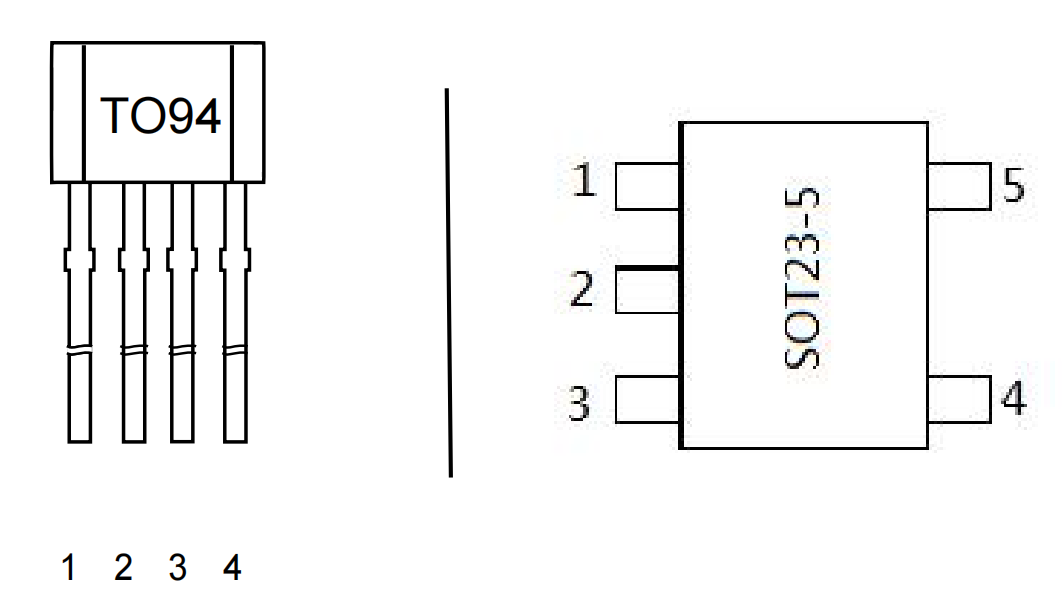
1. SOT23-5 SMD Package
| Pin No. | Symbol | Description |
|---|---|---|
| 1 | VCC | Positive DC supply input |
| 2 | NC | No connect; must be left floating |
| 3 | Vout | Gate drive output; connect to MOSFET/IGBT gate |
| 4 | GND | Ground |
| 5 | Vin | Logic signal input from MCU |
2. TO94 Through-Hole Package
| Pin No. | Symbol | Description |
|---|---|---|
| 1 | Vout | Gate drive output |
| 2 | VCC | Positive DC supply |
| 3 | Vin | Control signal input |
| 4 | GND | Ground |
Internal Block Diagram
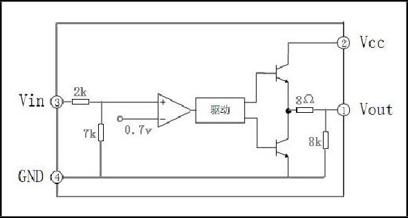
The IC integrates an internal reference comparator, driver buffer stage, complementary NPN/PNP push-pull output pair, and a built-in 8Ω output current-limiting resistor. The weak MCU logic signal is input through Vin, amplified in-phase, and output as a high-current drive signal from Vout—no external discrete amplification components are required.
Typical Application Circuit
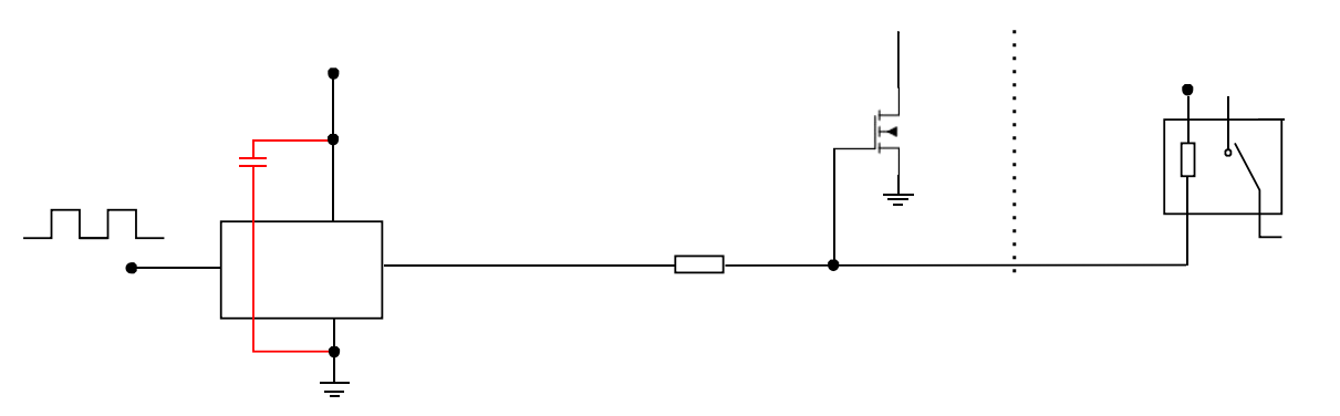
Standard application: Place a 0.1uF bypass capacitor between VCC and GND. Connect the MCU I/O directly to Vin. Connect Vout through a small series resistor to the gate of the N-Channel MOSFET/IGBT. For driving a DC relay, add a freewheeling diode between Vout and the relay coil to protect the IC. The NC pin must be left floating at all times—do not connect to ground or supply.
Target Applications
● Kitchen & Small Appliances: IGBT driver for induction cookers, power MOSFET control boards for blenders/soy milk makers, speed control circuits for food processors
● Switch-Mode Power Supplies: Low-voltage DC-DC converters, power switch drivers for small adapters
● Industrial Control Boards: Low-voltage N-Channel MOSFET switches, 5V/12V small DC relay drivers
● Small Variable-Frequency Equipment: Brushless fan drivers, miniature water pump power transistor drivers
Series Gate Driver IC Selection Guide
| Parameter / Model | N531 (Single-Channel Non-Inverting) | N532 (Single-Channel Inverting) | N534 (Dual-Channel Push-Pull) |
|---|---|---|---|
| Supply Voltage | 5~18V DC | 5~18V DC | 5~18V DC |
| Peak Drive Current | ±500mA | ±500mA | ±400mA per channel |
| Signal Phase | Non-Inverting | Inverting | Dual Independent Non-Inverting |
| Max Frequency | 350KHz | 350KHz | 250KHz |
| Package | SOT23-5 / TO94 | SOT23-5 | SOT23-6 |
Advantages Over Discrete Push-Pull Circuits
A single N531 IC replaces a traditional push-pull amplifier circuit built with 2 NPN, 2 PNP transistors, and 2 voltage-divider resistors, delivering significant design optimization.
● BOM Reduction: Replaces 6 discrete components with 1 IC, reducing procurement and assembly costs by over 60%
● Superior Consistency: Internal on-chip component matching eliminates batch-to-batch variation issues common with discrete transistors
● Smaller PCB Footprint: SOT23-5 SMD package occupies far less space than discrete component layouts
● Simplified Tuning: No need to adjust base current-limiting resistors; stable power device drive from power-on
● Lower Failure Rate: Reduces potential failure points from multiple solder joints and leakage paths
Authorized Distributor & Technical Support
GSMicro Semiconductor is an official authorized distributor of the N531, stocking both SOT23-5 and TO94 package options. We provide complimentary datasheets, reference schematics, and PCB layout guidelines. Support includes sample requests, pilot production runs, and long-term high-volume supply. Our application engineers offer one-on-one technical assistance for IGBT/MOSFET driver circuit debugging and EMC optimization, serving customers across small appliances, industrial power supplies, and variable-frequency equipment industries.
Frequently Asked Questions
Q: Can the N531 drive PMOS power transistors?
Q: How should the NC pin be handled? Can it be grounded?
Q: What is the maximum switching frequency when driving large-capacitance IGBTs?
Q: How can I request samples and obtain the datasheet?
- Grade And Comment
- Question And Answer