


GSMicro Primary Agent DC Gate Driver N532
- Model:
- N532
- Brand:
- GSMicro
- Batch No:
- N532,N532栅极驱动IC,N532 IGBT驱动,N532 MOSFET驱动,功率开关控制器,带使能驱动IC,SOT23-5驱动芯片,替代分立推挽电路,广晟微,小家電驱动,工業驅動
- Desc:
- N532 single-channel power switch controller, 5-18V, ±500mA peak drive, non-inverting, 5Ω output, enable control, 500KHz, supports 1200V/25A IGBT/MOSFET, SOT23-5, direct replacement for discrete circuits, from GSMicro.
- Stock:
- 210000 只
N532 Single-Channel Power Switch Controller | IGBT/MOSFET Driver IC with Enable Control
The N532 is a versatile power switch controller that replaces push-pull circuits built with discrete components. It can directly drive IGBTs, power MOSFETs, relays, and other power switches. Operating from a 5~18V wide DC supply, the device features non-inverting input-to-output signal transmission, a built-in 5Ω output resistor, and an integrated enable control pin (ENA) for system-level power management. Housed in a compact SOT23-5 package, it is widely used in home appliance control boards, industrial drives, switch-mode power supplies, and more.
※ Note: The IC is designed for N-Channel power devices only. For driving high-voltage high-current IGBTs, an operating frequency ≤50KHz is recommended to minimize switching losses.
Full Product Description: The N532 comes in a SOT23-5 SMD package with built-in output current limiting and a 5Ω matching resistor, requiring only a single bypass capacitor for stable operation. The input and output signals are in-phase, eliminating the need for external inverter circuits. The enable control pin (ENA) allows high-level enable and low-level shutdown, facilitating system standby or fault protection. With ±500mA drive current, the IC can quickly charge and discharge gate capacitances, effectively reducing power device switching losses. The device is mature in high-volume production, RoHS compliant, and offers a cost-effective alternative to discrete transistor push-pull circuits.
N532 Package & Packaging Ordering Information
| Part Number | Marking | Package | Standard Packing |
|---|---|---|---|
| N532 | N532 | SOT23-5 | 3000 pcs/reel |
Key Features & Benefits
● 5~18V wide DC supply, compatible with common 12V/15V auxiliary supplies; no additional voltage regulator required
● Push-pull output with 500mA source and sink capability for fast driving of large capacitive loads
● Built-in 5Ω output resistor eliminates the need for external gate current-limiting resistors, simplifying design
● Enable control pin (ENA): high level for normal operation, low level for output shutdown, facilitating system power saving and protection
● Non-inverting input-to-output, allowing direct replacement of discrete push-pull circuits without modifying control logic
● Up to 500KHz switching frequency (1nF load) to meet high-frequency application requirements
● SOT23-5 ultra-compact package saves PCB space, ideal for space-constrained designs
● -40℃~+85℃ wide operating temperature range (storage temperature -55~+150℃), industrial-grade reliability
Key Electrical Specifications
| Parameter | Typical Value | Unit |
|---|---|---|
| DC Supply Voltage VCC | 5~18 (Abs Max 24) | V |
| Peak Push-Pull Drive Current | ±500 | mA |
| Input Turn-On Threshold | 1.5~1.8 | V |
| Enable Voltage (ENA) | 3~5V Enable, 0V Shutdown | V |
| Quiescent Current | 1 (Typical) | μA |
| Input Impedance | 12~15 | kΩ |
| Rise/Fall Time (1nF Load) | 20~50 | ns |
| Max Switching Frequency (1nF Load) | 500 | KHz |
| Operating Temperature Range | -40 ~ +85 | ℃ |
| ESD Rating | 2000 | V |
AC Parameters (Ta=25℃)
| Parameter | Test Condition | Typical Value | Unit |
|---|---|---|---|
| Rise Delay TPHH | VCC=15V, CL=1nF | 1 | μs |
| Fall Delay TPLL | VCC=15V, CL=1nF | 1 | μs |
| Rise Time Tr | CL=1nF | 20~50 | ns |
| Fall Time Tf | CL=1nF | 20~50 | ns |
| Rise Time (10nF) | CL=10nF | 90~200* | ns |
| Fall Time (10nF) | CL=10nF | 110~250* | ns |
* When driving 1200V/20A IGBT, max rise time is 500ns, max fall time is 550ns.
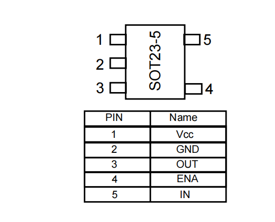
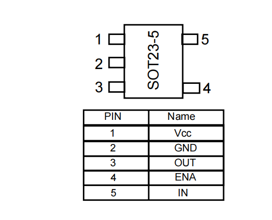
Pin Configuration (SOT23-5)
| Pin No. | Symbol | Description |
|---|---|---|
| 1 | VCC | Positive DC supply input (5~18V) |
| 2 | GND | Ground |
| 3 | OUT | Gate drive output; connect to MOSFET/IGBT gate |
| 4 | ENA | Enable control: High (3~5V) enables output, Low (0V) shuts down output |
| 5 | IN | Logic signal input from MCU |
Internal Block Diagram
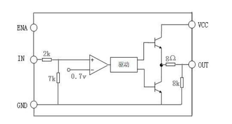
The IC integrates internal level shifting, driver buffer, complementary push-pull output pair, and a 5Ω output current-limiting resistor. The input signal is amplified in-phase to drive the output stage, with the ENA pin controlling output enable.
Typical Application Circuit
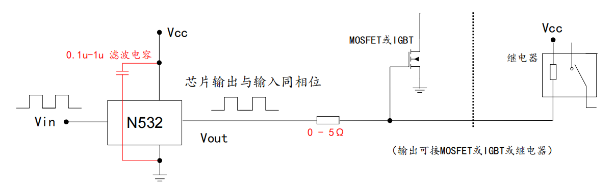
Application Notes:
1) Place a 0.1μF bypass capacitor between VCC and GND to filter high-frequency noise;
2) The output has a built-in 5Ω resistor; if drive performance is adequate, the external gate series resistor can be omitted;
3) Apply high level (3~5V) to ENA pin to enable output, low level (0V) to disable output;
4) Place the IC as close to the MCU as possible for more stable performance.
Target Applications
● Home Appliances: IGBT/MOSFET drivers for induction cookers, rice cookers, blenders, etc.
● Industrial Controls: Motor drives, solid-state relays, solenoid valve drivers
● Switch-Mode Power Supplies: DC-DC converters, adapter power switch drivers
● New Energy Equipment: Auxiliary drivers for EV chargers, photovoltaic inverters, etc.
Series Gate Driver IC Selection Guide
| Parameter / Model | N531 (Single-Channel Non-Inverting) | N532 (Single-Channel Non-Inverting + Enable) | N534 (Dual-Channel Push-Pull) |
|---|---|---|---|
| Supply Voltage | 5~18V | 5~18V | 5~18V |
| Peak Drive Current | ±500mA | ±500mA | ±400mA per channel |
| Signal Phase | Non-Inverting | Non-Inverting | Dual Independent Non-Inverting |
| Enable Control | No | Yes (ENA) | No |
| Built-in Output Resistor | 8Ω | 5Ω | — |
| Max Frequency | 350KHz | 500KHz (1nF) | 250KHz |
| Package | SOT23-5 / TO94 | SOT23-5 | SOT23-6 |
Advantages Over Discrete Push-Pull Circuits
A single N532 IC replaces a traditional push-pull amplifier circuit built with 2 NPN, 2 PNP transistors, and voltage-divider resistors, while adding an integrated enable control function.
● BOM Reduction: Replaces 6 discrete components with 1 IC, reducing procurement and assembly costs by over 60%
● Superior Consistency: On-chip matching eliminates batch-to-batch variation issues
● Smaller PCB Footprint: SOT23-5 occupies far less space than discrete component layouts
● Simplified Tuning: No need to adjust base current-limiting resistors; built-in 5Ω output resistor
● Lower Failure Rate: Reduces potential failure points from multiple solder joints and leakage paths
● Added enable control for system standby and fault protection
Authorized Distributor & Technical Support
GSMicro Semiconductor is an official authorized distributor of the N532, stocking SOT23-5 package in volume. We provide complimentary datasheets, reference schematics, and PCB layout guidelines. Support includes sample requests, pilot production runs, and long-term high-volume supply. Our application engineers offer one-on-one technical assistance for driver circuit debugging and EMC optimization, serving customers across home appliance, industrial power, and new energy industries.
Frequently Asked Questions
Q: How should the ENA pin of the N532 be used?
Q: Can the N532 drive PMOS?
Q: What are the main differences between N532 and N531?
Q: How can I request samples and obtain the datasheet?
- Grade And Comment
- Question And Answer